


产品分类
Hi-link BLE5.0 Wireless Bluetooth Module HLK-B26 Master-Slave Integrated Serial Port Transmission Support APP Low Power Consumption
BR/EDR and BLE dual-mode Bluetooth 5.0 wireless serial port transmission Bluetooth HLK-B50 master-slave integrated low-power bluetooth module
HLK-B20
HLK-B25
HLK-B50S
HLK-RM68
HLK-RM20
HLK-7612E
HLK-RM65
HLK-7628NE
HLK-RM60
GD01大板套件
HLK-7628N
HLK-7688A
HLK-RM08S
HLK-RM08K
HLK-7621
HLK-RM50
HLK-RM56
HLK-RM58N
HLK-RM28E
HLK-GD01
HLK-2M05
HLk-3W
HLK-PM01
HLK-5W-B Series
HLK-5M
10W-TL Series
10W-B Series
HLK-10M
HLK-15M
HLK-20M05
HLK-30M
HLK-30M
HLK-40M
HLK-22M05Z
HLK-2M03
HLK-2M09
HLK-2M12
HLK-2M24
HLK-2M15
HLK-PM03
HLK-PM09
HLK-PM12
HLK-PM15
HLK-PM24
HLK-3M05B
HLK-3M03B
HLK-3M09B
HLK-3M12B
HLK-3M15B
HLK-3M24B
HLK-3LD05
HLK-3LD09
HLK-3LD12
HLK-3LD24
HLK-3LD15
HLK-5LD05
HLK-5LD09
HLK-5LD12
HLK-5LD15
HLK-5LD24
HLK-3M05C
HLK-3M03C
HLK-3M09C
HLK-3M12C
HLK-3M24C
HLK-5M05
HLK-5M03
HLK-5M09
HLK-5M12
HLK-5M15
HLK-5M24
HLK-10M24T
HLK-5M24B
HLK-5M15B
HLK-5M12B
HLK-5M09B
HLK-5M05B
HLK-5M03B
HLK-10M03
HLK-10M05
HLK-10M09
HLK-10M12
HLK-10M15
HLK-10M24
HLK-10M24B
HLK-10M15B
HLK-10M12B
HLK-10M09B
HLK-10M05B
HLK-10M03B
HLK-10M05T
HLK-10M09T
HLK-10M12T
HLK-10M15T
HLK-10M03T
HLK-15M05C
HLK-15M09C
HLK-15M12C
HLK-15M15C
HLK-15M24C
HLK-20M09
HLK-20M12
HLK-20M15
HLK-20M24
HLK-3M15C
HLK-3LS03
HLK-3LS05
HLK-3LS09
HLK-3LS12
HLK-3LS15
HLK-3LS24
HLK-3LD05
HLK-3LD09
HLK-3LD12
HLK-3LD15
HLK-3LD24
HLK-5M03C
HLK-5M05C
HLK-5M09C
HLK-5M12C
HLK-5M15C
HLK-5M24C
HLK-5LS03
HLK-5LS05
HLK-5LS09
HLK-5LS12
HLK-5LS15
HLK-5LS24
HLK-10LS03
HLK-10LS05
HLK-10LS09
HLK-10LS12
HLK-10LS12
HLK-10LS15
HLK-10LS24
HLK-10M03C
HLK-10M05C
HLK-10M09C
HLK-10M12C
HLK-10M15C
HLK-10M24C
HLK-10LD03
HLK-10LD05
HLK-10LD09
HLK-10LD12
HLK-10LD15
HLK-10LD24
HLK-15M05B
HLK-15M09B
HLK-15M12B
HLK-15M15B
HLK-15M24B
HLK-15M12T
HLK-15LO09E
HLK-15LO12E
HLK-15LO15E
HLK-15LO24E
HLK-20M05C
HLK-20M09C
HLK-20M12C
HLK-20M15C
HLK-20M24C
HLK-20M09B
HLK-20M15B
HLK-30M09
HLK-30M12
HLK-30M15
HLK-30M24
HLK-30M09C
HLK-30M12C
HLK-30M15C
HLK-30M24C
HLK-30M09B
HLK-30M12B
HLK-30M15B
HLK-30M24B
HLK-40LC12
HLK-40LC15
HLK-40LC24
HLK-40M12C
HLK-40M15C
HLK-40M24C
HLK-12M12
HLK-40M12A
HLK-20EMI
HLK-50M05C
HLK-50M09C
HLK-50M12C
HLK-50M15C
HLK-50M18C
HLK-50M24C
HLK-60SR09
HLK-60SR12
HLK-60SR24
HLK-60SR24
HLK-24M12Z
HLK-30MxxZ
B0509S-1WR3
IA05XXS-1WR3 Series
F05XXS-1WR3
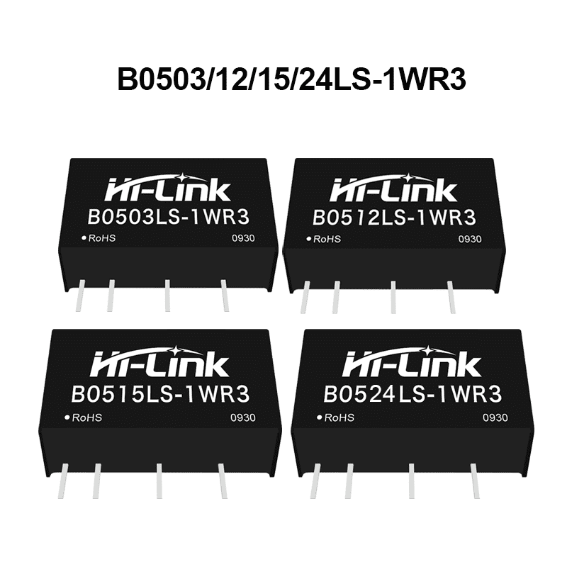
B05XXLS-1WR3
B12XXD-1WR3
B0505S-1WR3
B0505S-1WR2
B05XXS-1WR3
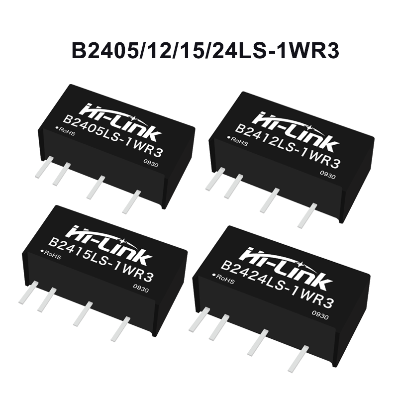
B24XXLS-1WR3
B24XXS-1WR3
XXS-1WR3
B24XXD-1WR3
F12XXS-1WR3
F15XXS-1WR3
LS-1WR3
IB05XXS-2WR3
S-2WR3
F05_S-2WR3 Series
B24xxS-2WR3
F12xxS-2WR3
B12xxS-2WR3
IBS-2WR3
B05_S-2WR3
B0505S-3WR3
URB24xxS-3WR3
WRB0505S-3WR3
URA24_S-3WR3
WRA24_S-3WR3
B24_S-3WR3
WRA12_S-3WR3
B12_S-3WR3
WRB12_S-3WR3
WRB48_S-3WR3
WRB24_S-3WR3
URA-YMD-5WR3
VRA-YMD-5WR3
VRB24_YMD-5WR3
VRA24_LD-10WR3
URB24_ZP-10WR3
VRB12_LD-10WR3
URA24_LD-10WR3
VRB_LD-10WR3
URA_YMD-10WR3
URB24_YMD-10WR3
VRB12_YMD-10WR3
URA_YMD-12W
URB_YMD-12WR3
VRB24_YMD-15WR3
URA24_YMD-15WR3
URB24_YMD-15WR3
URB24_YMD-20WR3
URA24_YMD-20WR3
URB24_LD-20WR3
URA1_LD-20WR3
URB_YMD-25WR3
URA24_YMD-25WR3
URA_LMD-30WR3
URB24_XLD-30WR3
URB24_LD-30WR3
URA_LD-30WR3
URB24_LMD-30WR3
VRB24_LMD-40WR3
URB_LMD-40WR3
URB48_LMD-50WR3
K78xx-500R3
RS485 Interface Isolated Module
B0303S-1WR3
B0305S-1WR3
B0503S-1WR3
B0512S-1WR3
B0515S-1WR3
B0524S-1WR3
B1203S-1WR3
B1205S-1WR3
B1209S-1WR3
B1212S-1WR3
B1215S-1WR3
B1224S-1WR3
B2403S-1WR3
B2405S-1WR3
B2409S-1WR3
B2412S-1WR3
B2415S-1WR3
B2424S-1WR3
B0503LS-1WR3
B0505LS-1WR3
B0509LS-1WR3
B0512LS-1WR3
B0515LS-1WR3
B0524LS-1WR3
IB05xxLS-1WR3
F24xxS-2WR3
A12xxS-2WR3
A24xxS-2WR3
URB48xxS-3WR3
UWB1205S-3WR3
UWB1212S-3WR3
UWB1215S-3WR3
VRB12xxYMD-5WR3
URB24xxYMD-5WR3
URB24xxS-6WR3
URB24xxYMD-20WR3-5pins
A05xxS-1WR3
A12xxS-1WR3
A24xxS-1WR3
F03xxS-1WR3
F24xxS-1WR3
F15xxS-2WR3
HLK-150Q-24S19A
HLK-150Q-24S24A
HLK-150Q-24S28A
HLK-150Q-48S24A
HLK-150Q-110S12A
HLK-150Q-110S24A
HLK-150Q-110S48
HLK-100Q-48S05A
HLK-100Q-110S05A
HLK-200Q-110S24
E05xxS-1WR3
E12xxS-1WR3
E24xxS-1WR3
LD020
HLK-LD012-5G 5.8G radar module
HLK-LD101V
HLK-LD101L
HLK-LD101
HLK-LD2460
HLK-LD2413 24GHz Radar Module Distance/Liquid Level Detection
HLK-LD2402
HLK-LD2401
HLK-LD2451
HLK-LD2415H
HLK-LD2412
HLK-LD2461 Kit
HLK-LD2410C Kit
HLK-LD2410B Kit
HLK-LD2450 Kit
HLK-LD2410S Kit
HLK-LD2450
HLK-LD2410S
HLK-LD2411S
HLK-LD2411
HLK-LD242
HLK-LD2410C
HLK-LD2410B
HLK-LD2412 Kit
HLK-LD2410
HLK-LD6001
HLK-LD6001C
HLK-LD6001A
HLK-LD6002H
HLK-LD8001B
HLK-LD8001
HLK-LD8001H
HLK-LD016
HLK-LD017
HLK-LD020
HLK-LD021
HLK-LD1010
HLK-LD1020
HLK-LD1030
HLK-LD1040
HLK-LD1041
HLK-LD2402G
HLK-LD2410D
HLK-LD2410D-B
HLK-LD2420
HLK-LD2450A
HLK-LD2452
HLK-LD2453
HLK-LD6001B
HLK-LD6004
HLK-LD7901B
HLK-LD6002
HLK-LD6002B
HLK-LD6002C
HLK-LD2410-AA
4G/6dBi 115mm
5G/5dBi 115mm
4G/5dBi 120mm
4G/5dBi 112mm
4G/5dBi 110mm
4G/5dBi 110mm 21 81
4G/3dBi 120mm 40 15
4G/3dBi 120mm24 53
4G/5dBi/13*66mm/146mm/PCB
4G/5dBi/15*105mm/120mm/PCB
4G/5dBi/14*125mm/120mm/PCB
4G/3dBi/10×44mm/145mm/PCB
4G/3dBi/47×7mm/120mm/FPC
NB-IoT/3dBi/17×50mm/125mm/FPC
NB-IoT/3dBi/17×50mm/125mm/FPC
NB-IoT/3dBi/17×50mm/125mm/FPC
NB-IoT/3dBi/17×50mm/125mm/FPC
NB-IoT/3dBi/10×44mm/120mm/FPC
NB-IoT/3dBi/22×43mm/115mm/FPC
NB-IoT/3dBi/8×33mm/100mm/FPC
NB-IoT/3dBi/7×34mm/120mm/FPC
NB-IoT / 3dBi / Diameter 41mm /140mm / PCB
NB-IoT/3dBi/13×40mm/148mm/PCB
NB-IoT/3dBi/8×35mm/147mm/PCB
NB-IoT/2dBi/8×66mm/140mm/PCB
4G/GSN/NB rubber duck antenna
4G/GSM/NB small suction cup antenna
4G/GSM/NB FRP antenna
Copper Rod Suction Cup Antenna
4G/GSM/NB cabinet antenna
4G/GSM/NB patch antenna
Suction cup antenna for 4G/GSM/NB
2.4G/5.8G Built-in Antenna
2.4G/5.8G Rubber Antenna
2.4G/5.8G suction cup antenna
2.4G stainless steel antenna
2.4G/5.8G fiberglass antenna
2.4G flat panel directional antenna
433M stainless steel antenna
433/470M FRP antenna
433M directional flat panel antenna
Built-in 433M antenna
433/470M glue stick antenna
433/470M suction cup antenna
433M Yagi antenna
100UF25V
1000UF25V
2200uf25v
25V 47UF~680UF
100UF25V
25V220UF
470UF100V
680UF 100V
16V2200UF
16V 220UF
470UF16V
16V1000UF
16V 47UF 100UF 330UF 680UF
330UF35V
35V 680UF
220UF 35V
35V 100UF
47UF~2200UF 35V
1000UF50V
2.2UF/4.7UF/10UF/22UF50V
50V680UF
470UF50V
330UF50V
220UF 100UF 50V
220UF 100UF 50V
10V100UF
1000UF/2200UF 10V
470UF10V
10V 220UF
400V 22UF 10UF 6.8UF 4.7UF
250V10UF
10V 1000UF 100UF
450V4.7UF
450V 15UF
100UF 400V
470UF25V
50V1000UF
16V220UF
450V 10UF
25V 680UF
35V470UF
50V 2200UF 470UF 100UF 220UF
25V220UF/100UF
33UF 400V
35V220uf/100uf
25V2200UF
3300UF35V
63V470UF
68UF450V
6.8UF450V
10UF500V
200V 4.7UF 10UF 22UF 33UF 47UF 100UF 220UF
250V10UF
250V 2.2UF 22UF 47UF 100UF 220UF
250V 4.7UF
330V 600UF
150UF 330V
330V 80UF
750UF330V
330V 120UF
180UF330V
330V 220UF
300UF 330V
400V100UF
400V220UF
33UF 400V
400V82UF
2.2UF 400V
68UF400V
400V15UF
400V10UF
6.8UF400V
400V47UF
22UF 400V
400V 4.7UF
500V 4.7UF
450V4.7UF
220UF450V
4.7UF 450V Lead Type Capacitor
6.8UF450V
22UF450V
10UF450V
450V 2.2UF
450V47UF
X2-123K/275V/310V
X2-153K/275V/310V
X2-225K/275V/310V
X2-334K/275V/310V
X2-474K/275V/310V
X2-684K/275V/310V
X2-824K/275V/310V
X2-224K/275V/310V
X2-105K/275V/310V
X2-274K/275V/310V
X2-564K/275V/310
101 1KV
392 1kv
471 1kv
472 1kv
561 1kv
681 1kv
102K-10KV
332K-10KV
471K-10KV
472K-10KV
681K-10KV
682K-10KV
102K-15KV
103K-15KV
221K-15KV
222K-15KV
331K-15KV
332K-15KV
102K-40KV
101K-40KV
222K-40KV
251K-40KV
501K-40KV
101K-10KV
103M-30KV
331M-30KV
332M-30KV
471M-30KV
472M-30KV
681M-30KV
222M-50KV
102M-50KV
251M-50KV
501M-50KV
471K-2KV
392K-2KV
472K-2KV
561K-2KV
681K-2KV
471K-15KV
472K-15KV
681K-15KV
102K-20KV
471K-20KV
472K-20KV
501K-20KV
681K-20KV
682K-20KV
221K-1KV
221K-20KV
222K-10KV
101K-15KV
3300uF 80V CER
4700uF 80V CER
5600uF 80V CER
6800uF 80V CER
8200uF 80V CER
10000uF 100V CER
22000uF 80V CER
3300uF 80V CHA
4700uF 80V CHA
5600uF 80V CHA
6800uF 80V CHA
8200uF 80V CHA
10000uF 100V CHA
22000uF 100V CHA
10D102K
10D180K
05D511K
05D301K
05D330K
14D181K
10D121K
10D201K
10D220K
10D511K
10D560K
5D121K
05D241K
05D270K
05D221K
05D331K
05D361K
05D391K
05D431K
05D561K
07D270K
07D820K
07D681K
07D751K
07D101K
07D121K
07D151K
07D221K
07D361K
07D390K
07D241K
07D391K
07D431K
07D331K
10D361K
10D221K
07D561K
07D621K
07D471K
10D101K
10D112K
10D241K
10D271K
10D270K
10D751K
10D820K
10D681K
10D391K
10D431K
14D180K
20D561K
20D301K
20D330K
14D121K
14D471K
14D201K
15D-7
18D-7
20D-7
22D-7
30D-7
33D-7
47D-15
16D-15
18D-15
20D-15
22D-15
25D-15
4.7D-13
4D-13
5D-13
6.8D-13
6D-13
7D-13
7D-11
8D-11
10D-11
12D-11
15D-11
16D-11
5D-11
22D-11
25D-11
30D-11
33D-11
47D-11
5D-9
6D-9
7D-9
8D-9
10D-9
12D-9
10D-7
3D-7
4D-7
5D-7
6D-7
7D-7
2.5D-11
2D-11
3D-11
4D-11
1.5D-13
2.5D-13
3D-13
10D-25
16D-25
18D-25
0.7D-25
1.3D-25
1.5D-25
30D-15
33D-15
25D-13
8D-13
10D-13
12D-13
7D-15
1.5D-15
2.5D-15
3D-15
4.7D-15
4D-15
5D-20
6.8D-20
6D-20
7D-20
8D-20
10D-20
15D-15
6D-15
8D-15
10D-15
12D-15
15D-13
16D-13
18D-13
1D-20
2.2D-20
2.5D-20
3D-20
4D-20
5D-25
6D-25
7D-25
8D-25
12D-25
5D-15
6.8D-15
15D-9
16D-9
18D-9
20D-9
22D-9
8D-7
12D-7
16D-7
50D-11
18D-11
20D-11
12D-20
CBB21-474J/630V
CBB23-102J/1000V
CBB21-224J/630V
CBB21-823J/630V
CBB21-154J/630V
CBB21-104J/630V
CBB21-562J450V
CBB21-155J/450V
CBB21-474J450V
CBB21-273J/630V
CBB21-154J/450V
CBB21-225J/450V
CBB21-155J/630V
CBB21-475J/630V
CL21-684J/630V
CL21-103J/630V
CBB21-274J/450V
CL21-104J/630V
CBB21-105J/450V
CBB21-333J/630V
CBB21-102J/250V
CBB21-103J/250V
CBB21-104J/250V
CBB21-105J/250V
CBB21-123J/250V
CBB21-183J/630V
CBB21-184J/630V
CBB21-222J/630V
CBB21-223J/630V
CBB81-224J/1000V
CBB81-102J/1000V
CBB81-103J/1000V
CBB81-104J/1000V
CBB81-153J/1000V
CBB21-104/450V
CBB21-123J/450V
CBB21-124J/450V
CBB21-125J/450V
CBB21-105J/400V
CBB21-123J/400V
CBB21-124J/400V
CBB21-125J/400V
CBB21-135J/400V
CBB21-135J/450V
CBB21-145J/450V
CBB21-153J/450V
CBB81-223J/1000V
CBB81-332J/1000V
CBB21-123J/630V
CBB21-105J/630V
CBB21-124J/630V
CBB21-125J/630V
CBB21-225/400V
CBB21-274J/400V
CBB21-332J/400V
CBB21-333J/400V
CBB21-334J/400V
CBB21-104/400V
CBB21-682J/450V
CBB21-683J/450V
CBB21-684J/450V
CBB21-823J/450V
CBB21-154J/400V
CBB21-155J/400V
CBB21-182J/400V
CBB21-222J/400V
105K/50V/100V
106K/50V/100V
221K/50V/100V
225K/50V/100V
683K/50V/100V
104K/50V/100V
122K/50V/100V
222K/50V/100V
684K/50V/100V
102K/50V/100V
103K/50V/100V
154K/50V/100V
334K/50V/100V
224K/50V/100V
201K/50V/100V
475K/50V/100V
3F/2.7V
10F/2.7V
90F/2.7V
6F/2.7V
200F/2.7V
40F/2.7V
30F/2.7V
150F/2.7V
15F/2.7V
400F/2.7V
50F/2.7V
8F/2.7V
4.7F/2.7V
2F/2.7V
1F/2.7V
100F/2.7V
2.7V 100F Black cylindrical shape
2.7V 120F Black cylindrical shape
2.7V 150F Black cylindrical shape
2.7V 200F Black cylindrical shape
2.7V 300F Black cylindrical shape
2.7V 400F Black cylindrical shape
2.7V 20F Black cylindrical shape
2.7V 30F Black cylindrical shape
2.7V 40F Black cylindrical shape
2.7V 50F Black cylindrical shape
2.7V 90F Black cylindrical shape
0.1F 5.5V Black button type
0.22F 5.5V Black button type
0.33F 5.5V Black button type
0.47F 5.5V Black button type
0.68F 5.5V Black button type
1.5F 5.5V Black button type
1F 5.5V Black button type
4F 5.5V Black button type
0.47F 5.5V Black modular type
1.5F 5.5V Black modular type
1F 5.5V Black modular type
2F 5.5V Black modular type
5F 5.5V Black modular type
0.47F 5V Black modular type
1.5F 5V Black modular type
1F 5V Black modular type
2F 5V Black modular type
10000uF/25V
3300uF/25V
680uF/200V
2200uF/200V
220uF/400V
220uF/450V
22000uF/25V
12000uF/25V
15000uF/25V
27000uF/25V
33000uF/25V
10000uF/35V
12000uF/35V
15000uF/35V
18000uF/35V
22000uF/35V
27000uF/35V
4700uF/50V
5600uF/50V
6800uF/50V
8200uF/50V
10000uF/50V
12000uF/50V
15000uF/50V
6800uF/63V
2200uF/63V
2700uF/63V
3300uF/63V
3900uF/63V
4700uF/63V
15000uF/63V
5600uF/63V
8200uF/63V
10000uF/63V
12000uF/63V
3300uF/80V
1000uF/80V
1200uF/80V
1500uF/80V
1800uF/80V
2200uF/80V
6800uF/80V
2700uF/80V
3300uF/100V
560uF/100V
680uF/100V
820uF/100V
1000uF/100V
1200uF/100V
22000uF/40V
680uF/50V
1000uF/50V
1200uF/50V
1500uF/50V
1800uF/50V
4700uF/160V
1000uF/160V
1200uF/160V
1500uF/160V
1800uF/160V
150uF/160V
820uF/160V
390uF/220V
470uF/220V
560uF/220V
820uF/220V
470uF/250V
560uF/250V
680uF/250V
820uF/250V
1000uF/250V
1200uF/250V
270uF/400V
330uF/400V
390uF/400V
470uF/400V
68uF/400V
180uF/450V
270uF/450V
330uF/450V
390uF/450V
470uF/450V
680uF/450V
220000uf/50V RK
3900uf/50V RK
4700uf/50V RK
5600uf/50V RK
6800uf/50V RK
8200uf/50V RK
10000uf/200V
10000uf/200V
680uf/200V RK
820uf/200V RK
1000uf/200V RK
1200uf/200V RK
1500uf/200V RK
4700uF/400V RK
150uF/400V RK
180uF/400V RK
220uF/400V RK
270uF/400V RK
330uF/400V RK
8200uF/400V RK
390uF/400V RK
4700uF/450V RK
56uF/450V RK
68uF/450V RK
82uF/450V RK
100uF/450V RK
120uF/450V RK
8200uF/450V RK
150uF/450V RK
180uF/450V RK
220uF/450V RK
270uF/450V RK
330uF/450V RK
2200uF/450V RK
390uF/450V RK
470uF/450V RK
560uF/450V RK
10000uF/450V RK
22000uF/450V RK
33uF/450V RK
1000uF/6.3V
1500uF/6.3V
2200uF/6.3V
3300uF/6.3V
4700uF/6.3V
6800uF/6.3V
8200uF/6.3V
10000uF/6.3V
12000uF/6.3V
15000uF/6.3V
22000uF/6.3V
330uF/16V
470uF/16V
560uF/16V
680uF/16V
820uF/16V
68uF/16V
1500uF/16V
1500uF/25V
390uF/25V
470uF/25V
560uF/25V
680uF/25V
820uF/25V
3.3uF/35V
4.7uF/35V
6.8uF/35V
10uF/35V
22uF/35V
47uF/63V
56uF/63V
68uF/63V
100uF/63V
220uF/63V
330uF/63V
33uF/63V
470uF/100V
33uF/100V
47uF/100V
56uF/100V
68uF/100V
100uF/100V
100uF/160V
3.3uF/160V
4.7uF/160V
6.8uF/160V
10uF/160V
15uF/160V
33uF/160V
47uF/160V
68uF/160V
120uF/160V
2.2uF/200V
3.3uF/200V
4.7uF/200V
6.8uF/200V
33uF/250V
2.2uF/250V
3.3uF/250V
4.7uF/250V
6.8uF/250V
10uF/250V
100uF/350V
33uF/350V
47uF/350V
68uF/350V
120uF/350V
82uF/400V
15uF/400V
22uF/400V
33uF/400V
47uF/400V
1uF/450V
3.3uF/450V
4.7uF/450V
6.8uF/450V
8.2uF/450V
47uF/450V
33uF/450V
56uF/450V
68uF/450V
82uF/450V
10uF/500V
56uF/500V
68uF/500V
820UF/2.5V MA
220UF/2.5V MA
150UF/2.5V MA
1200UF/2.5V MA
1500UF/2.5V MA
82UF/20V MA
100UF/20V MA
120UF/20V MA
150UF/20V MA
6.8UF/25V MA
10UF/25V MA
22UF/25V MA
1200UF/2.5V PA
1500UF/2.5V PA
270UF/2.5V PA
330UF/2.5V PA
390UF/2.5V PA
560UF/2.5V PA
270UF/4V PA
330UF/4V PA
390UF/4V PA
560UF/4V PA
680UF/4V PA
820UF/4V PA
470UF/6.3V PA
560UF/6.3V PA
680UF/6.3V PA
150UF/6.3V PA
220UF/6.3V PA
270UF/6.3V PA
100UF/16V PA
120UF/16V PA
150UF/16V PA
180UF/16V PA
220UF/16V PA
270UF/16V PA
10UF/25V PA
22UF/25V PA
33UF/25V PA
47UF/25V PA
56UF/25V PA
100UF/25V PA
B24XXLS-1WR3 B05XXLS-1WR3
0个评价 | 0人购买
型号
B05XXLS-1WR3
B24XXLS-1WR3
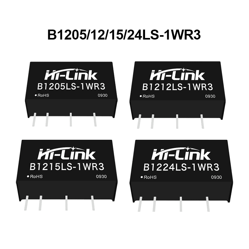
B12XXLS-1WR3
促销
产品推荐
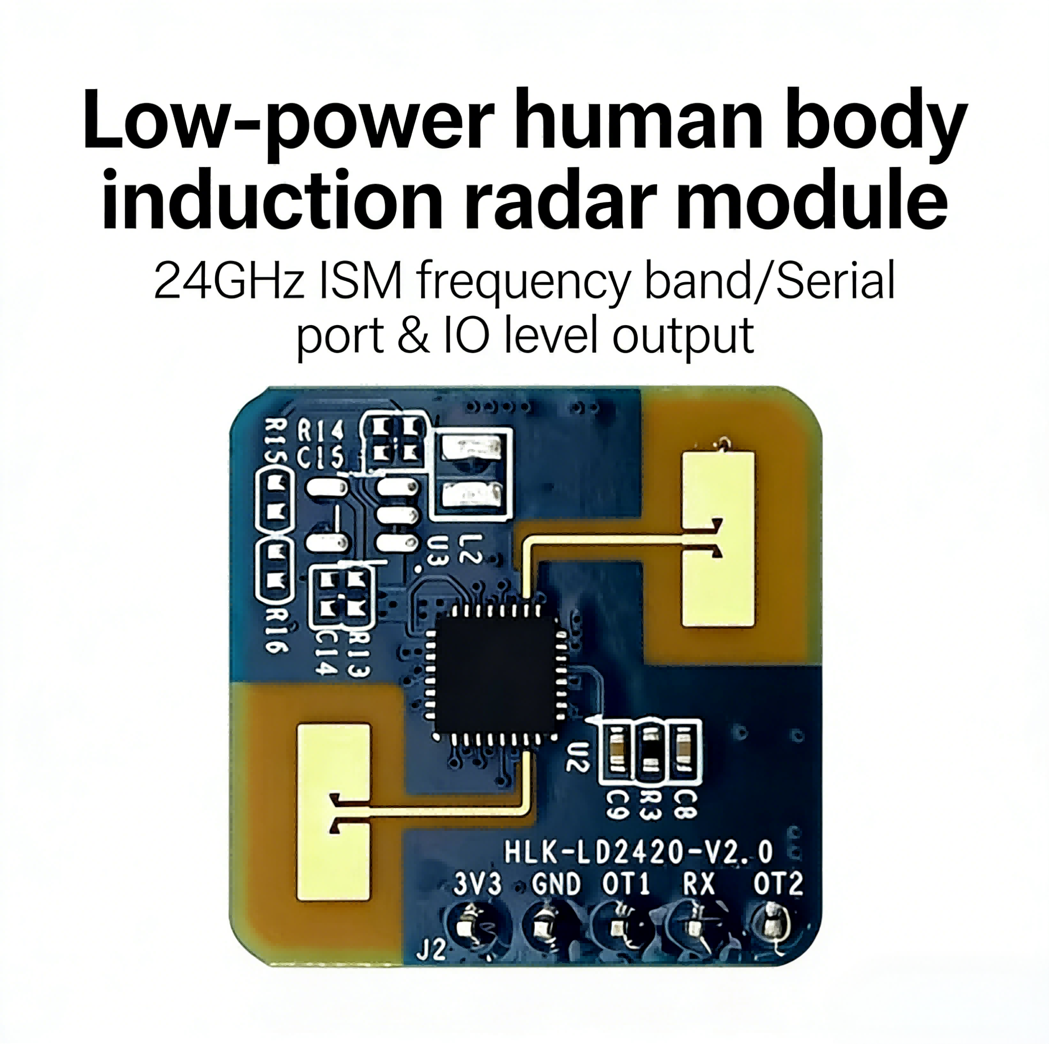
Hailingke 24G millimeter-wave radar LD2420 human body micro-motion and movement sensing module intelligent sensor
0人购买
$1.50
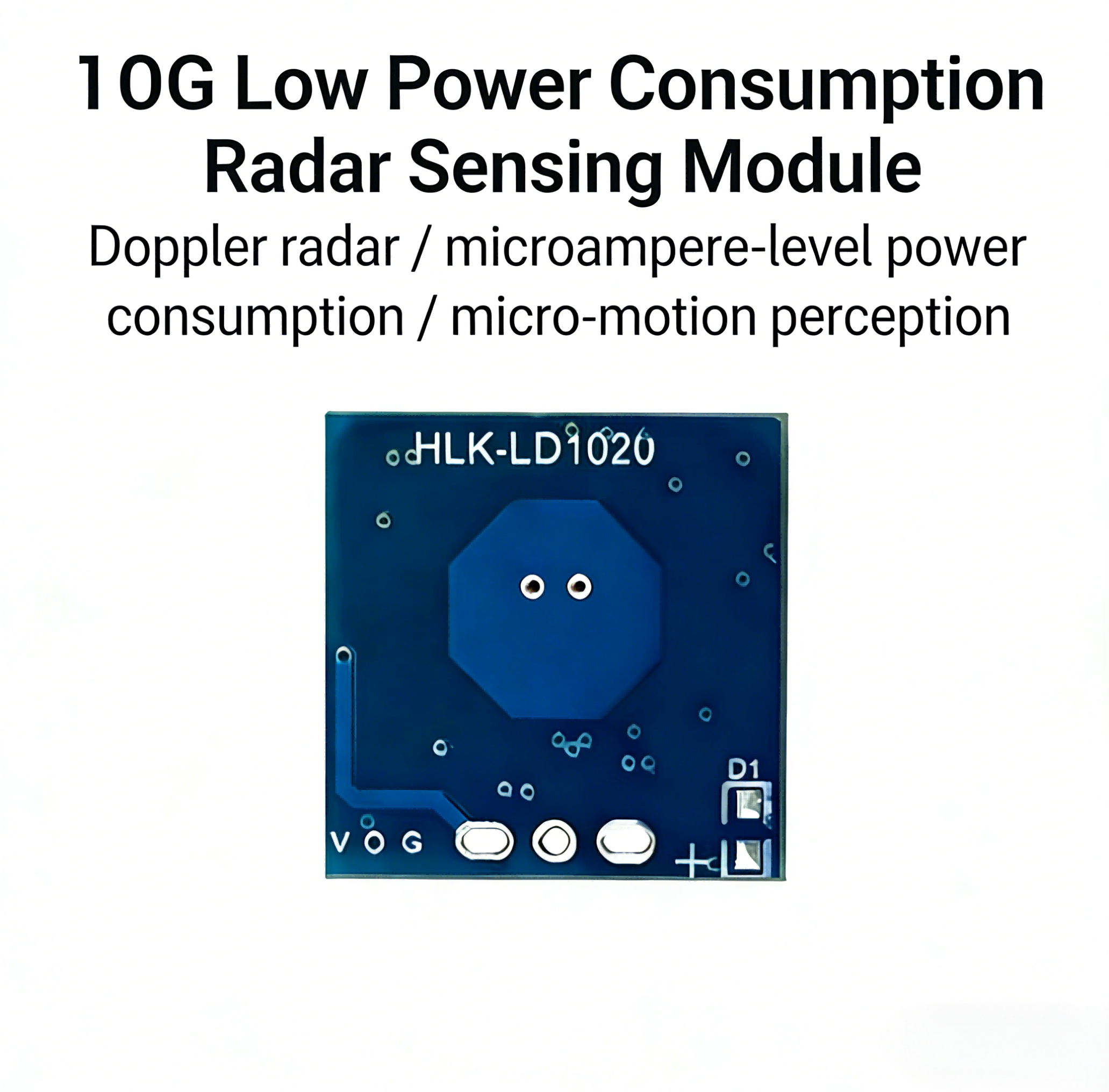
Hailingke 10G microwave radar sensor module LD1020 intelligent sensor
0人购买
$0.60
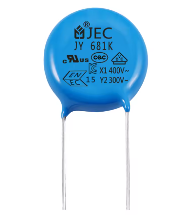
Safety Ceramic Disc Y2 Capacitor 300V 681K ceramic safety capacitor for ac decoupling cross jec capacitor
0人购买
价格详谈
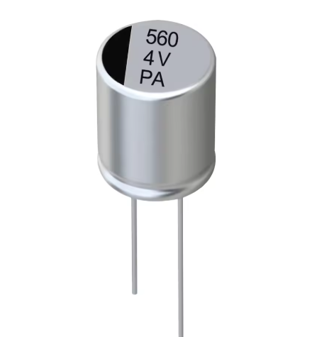
Hight Quality & Hot Sale Szwx Aluminum For Led Suppliers Surface Mount 560UF/4V Electrolytic Capacitor capacitors old
0人购买
价格详谈
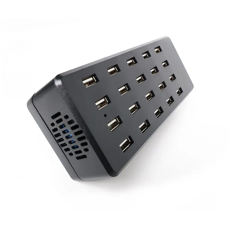
DINGKKE USB Multi-port Charger, USB Power Supply, 20-port Charging Head, Plastic Multi-port Mobile Phone Charger, OEM/ODM
0人购买
$11.95
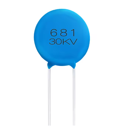
Electronic Component Ultra High Voltage Film Ceramic Capacitor 681 High Voltage Ceramic Capacitor 30kv
0人购买
价格详谈


购物指南
服务申明
快递
支持七天无理由退货
如果快递丢失,支持退货
如果快递损坏,支持退货
支持90天内免费换货
安全与隐私
安全付款:未经您的同意,我们不会与任何第三方分享您的个人信息。
安全的个人资料:我们保护您的隐私,确保您的个人资料安全可靠。
支付安全
与受欢迎的支付合作伙伴合作,您的个人信息是安全的。