


产品分类
Hi-link BLE5.0 Wireless Bluetooth Module HLK-B26 Master-Slave Integrated Serial Port Transmission Support APP Low Power Consumption
BR/EDR and BLE dual-mode Bluetooth 5.0 wireless serial port transmission Bluetooth HLK-B50 master-slave integrated low-power bluetooth module
HLK-B20
HLK-B25
HLK-B50S
HLK-RM68
HLK-RM20
HLK-7612E
HLK-RM65
HLK-7628NE
HLK-RM60
GD01大板套件
HLK-7628N
HLK-7688A
HLK-RM08S
HLK-RM08K
HLK-7621
HLK-RM50
HLK-RM56
HLK-RM58N
HLK-RM28E
HLK-GD01
HLK-2M05
HLk-3W
HLK-PM01
HLK-5W-B Series
HLK-5M
10W-TL Series
10W-B Series
HLK-10M
HLK-15M
HLK-20M05
HLK-30M
HLK-30M
HLK-40M
HLK-22M05Z
HLK-2M03
HLK-2M09
HLK-2M12
HLK-2M24
HLK-2M15
HLK-PM03
HLK-PM09
HLK-PM12
HLK-PM15
HLK-PM24
HLK-3M05B
HLK-3M03B
HLK-3M09B
HLK-3M12B
HLK-3M15B
HLK-3M24B
HLK-3LD05
HLK-3LD09
HLK-3LD12
HLK-3LD24
HLK-3LD15
HLK-5LD05
HLK-5LD09
HLK-5LD12
HLK-5LD15
HLK-5LD24
HLK-3M05C
HLK-3M03C
HLK-3M09C
HLK-3M12C
HLK-3M24C
HLK-5M05
HLK-5M03
HLK-5M09
HLK-5M12
HLK-5M15
HLK-5M24
HLK-10M24T
HLK-5M24B
HLK-5M15B
HLK-5M12B
HLK-5M09B
HLK-5M05B
HLK-5M03B
HLK-10M03
HLK-10M05
HLK-10M09
HLK-10M12
HLK-10M15
HLK-10M24
HLK-10M24B
HLK-10M15B
HLK-10M12B
HLK-10M09B
HLK-10M05B
HLK-10M03B
HLK-10M05T
HLK-10M09T
HLK-10M12T
HLK-10M15T
HLK-10M03T
HLK-15M05C
HLK-15M09C
HLK-15M12C
HLK-15M15C
HLK-15M24C
HLK-20M09
HLK-20M12
HLK-20M15
HLK-20M24
HLK-3M15C
HLK-3LS03
HLK-3LS05
HLK-3LS09
HLK-3LS12
HLK-3LS15
HLK-3LS24
HLK-3LD05
HLK-3LD09
HLK-3LD12
HLK-3LD15
HLK-3LD24
HLK-5M03C
HLK-5M05C
HLK-5M09C
HLK-5M12C
HLK-5M15C
HLK-5M24C
HLK-5LS03
HLK-5LS05
HLK-5LS09
HLK-5LS12
HLK-5LS15
HLK-5LS24
HLK-10LS03
HLK-10LS05
HLK-10LS09
HLK-10LS12
HLK-10LS12
HLK-10LS15
HLK-10LS24
HLK-10M03C
HLK-10M05C
HLK-10M09C
HLK-10M12C
HLK-10M15C
HLK-10M24C
HLK-10LD03
HLK-10LD05
HLK-10LD09
HLK-10LD12
HLK-10LD15
HLK-10LD24
HLK-15M05B
HLK-15M09B
HLK-15M12B
HLK-15M15B
HLK-15M24B
HLK-15M12T
HLK-15LO09E
HLK-15LO12E
HLK-15LO15E
HLK-15LO24E
HLK-20M05C
HLK-20M09C
HLK-20M12C
HLK-20M15C
HLK-20M24C
HLK-20M09B
HLK-20M15B
HLK-30M09
HLK-30M12
HLK-30M15
HLK-30M24
HLK-30M09C
HLK-30M12C
HLK-30M15C
HLK-30M24C
HLK-30M09B
HLK-30M12B
HLK-30M15B
HLK-30M24B
HLK-40LC12
HLK-40LC15
HLK-40LC24
HLK-40M12C
HLK-40M15C
HLK-40M24C
HLK-12M12
HLK-40M12A
HLK-20EMI
HLK-50M05C
HLK-50M09C
HLK-50M12C
HLK-50M15C
HLK-50M18C
HLK-50M24C
HLK-60SR09
HLK-60SR12
HLK-60SR24
HLK-60SR24
HLK-24M12Z
HLK-30MxxZ
B0509S-1WR3
IA05XXS-1WR3 Series
F05XXS-1WR3
B05XXLS-1WR3
B12XXD-1WR3
B0505S-1WR3
B0505S-1WR2
B05XXS-1WR3
B24XXLS-1WR3
B24XXS-1WR3
XXS-1WR3
B24XXD-1WR3
F12XXS-1WR3
F15XXS-1WR3
LS-1WR3
IB05XXS-2WR3
S-2WR3
F05_S-2WR3 Series
B24xxS-2WR3
F12xxS-2WR3
B12xxS-2WR3
IBS-2WR3
B05_S-2WR3
B0505S-3WR3
URB24xxS-3WR3
WRB0505S-3WR3
URA24_S-3WR3
WRA24_S-3WR3
B24_S-3WR3
WRA12_S-3WR3
B12_S-3WR3
WRB12_S-3WR3
WRB48_S-3WR3
WRB24_S-3WR3
URA-YMD-5WR3
VRA-YMD-5WR3
VRB24_YMD-5WR3
VRA24_LD-10WR3
URB24_ZP-10WR3
VRB12_LD-10WR3
URA24_LD-10WR3
VRB_LD-10WR3
URA_YMD-10WR3
URB24_YMD-10WR3
VRB12_YMD-10WR3
URA_YMD-12W
URB_YMD-12WR3
VRB24_YMD-15WR3
URA24_YMD-15WR3
URB24_YMD-15WR3
URB24_YMD-20WR3
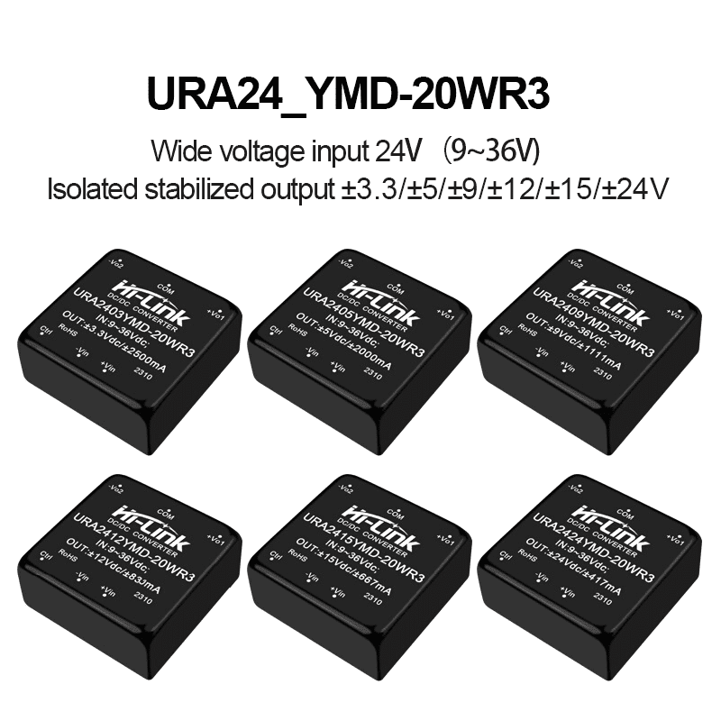
URA24_YMD-20WR3
URB24_LD-20WR3
URA1_LD-20WR3
URB_YMD-25WR3
URA24_YMD-25WR3
URA_LMD-30WR3
URB24_XLD-30WR3
URB24_LD-30WR3
URA_LD-30WR3
URB24_LMD-30WR3
VRB24_LMD-40WR3
URB_LMD-40WR3
URB48_LMD-50WR3
K78xx-500R3
RS485 Interface Isolated Module
B0303S-1WR3
B0305S-1WR3
B0503S-1WR3
B0512S-1WR3
B0515S-1WR3
B0524S-1WR3
B1203S-1WR3
B1205S-1WR3
B1209S-1WR3
B1212S-1WR3
B1215S-1WR3
B1224S-1WR3
B2403S-1WR3
B2405S-1WR3
B2409S-1WR3
B2412S-1WR3
B2415S-1WR3
B2424S-1WR3
B0503LS-1WR3
B0505LS-1WR3
B0509LS-1WR3
B0512LS-1WR3
B0515LS-1WR3
B0524LS-1WR3
IB05xxLS-1WR3
F24xxS-2WR3
A12xxS-2WR3
A24xxS-2WR3
URB48xxS-3WR3
UWB1205S-3WR3
UWB1212S-3WR3
UWB1215S-3WR3
VRB12xxYMD-5WR3
URB24xxYMD-5WR3
URB24xxS-6WR3
URB24xxYMD-20WR3-5pins
A05xxS-1WR3
A12xxS-1WR3
A24xxS-1WR3
F03xxS-1WR3
F24xxS-1WR3
F15xxS-2WR3
HLK-150Q-24S19A
HLK-150Q-24S24A
HLK-150Q-24S28A
HLK-150Q-48S24A
HLK-150Q-110S12A
HLK-150Q-110S24A
HLK-150Q-110S48
HLK-100Q-48S05A
HLK-100Q-110S05A
HLK-200Q-110S24
E05xxS-1WR3
E12xxS-1WR3
E24xxS-1WR3
LD020
HLK-LD012-5G 5.8G radar module
HLK-LD101V
HLK-LD101L
HLK-LD101
HLK-LD2460
HLK-LD2413 24GHz Radar Module Distance/Liquid Level Detection
HLK-LD2402
HLK-LD2401
HLK-LD2451
HLK-LD2415H
HLK-LD2412
HLK-LD2461 Kit
HLK-LD2410C Kit
HLK-LD2410B Kit
HLK-LD2450 Kit
HLK-LD2410S Kit
HLK-LD2450
HLK-LD2410S
HLK-LD2411S
HLK-LD2411
HLK-LD242
HLK-LD2410C
HLK-LD2410B
HLK-LD2412 Kit
HLK-LD2410
HLK-LD6001
HLK-LD6001C
HLK-LD6001A
HLK-LD6002H
HLK-LD8001B
HLK-LD8001
HLK-LD8001H
HLK-LD016
HLK-LD017
HLK-LD020
HLK-LD021
HLK-LD1010
HLK-LD1020
HLK-LD1030
HLK-LD1040
HLK-LD1041
HLK-LD2402G
HLK-LD2410D
HLK-LD2410D-B
HLK-LD2420
HLK-LD2450A
HLK-LD2452
HLK-LD2453
HLK-LD6001B
HLK-LD6004
HLK-LD7901B
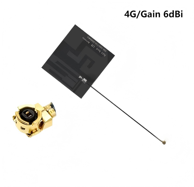
4G/6dBi 115mm
5G/5dBi 115mm
4G/5dBi 120mm
4G/5dBi 112mm
4G/5dBi 110mm
4G/5dBi 110mm 21 81
4G/3dBi 120mm 40 15
4G/3dBi 120mm24 53
4G/5dBi/13*66mm/146mm/PCB
4G/5dBi/15*105mm/120mm/PCB
4G/5dBi/14*125mm/120mm/PCB
4G/3dBi/10×44mm/145mm/PCB
4G/3dBi/47×7mm/120mm/FPC
NB-IoT/3dBi/17×50mm/125mm/FPC
NB-IoT/3dBi/17×50mm/125mm/FPC
NB-IoT/3dBi/17×50mm/125mm/FPC
NB-IoT/3dBi/17×50mm/125mm/FPC
NB-IoT/3dBi/10×44mm/120mm/FPC
NB-IoT/3dBi/22×43mm/115mm/FPC
NB-IoT/3dBi/8×33mm/100mm/FPC
NB-IoT/3dBi/7×34mm/120mm/FPC
NB-IoT / 3dBi / Diameter 41mm /140mm / PCB
NB-IoT/3dBi/13×40mm/148mm/PCB
NB-IoT/3dBi/8×35mm/147mm/PCB
NB-IoT/2dBi/8×66mm/140mm/PCB
4G/GSN/NB rubber duck antenna
4G/GSM/NB small suction cup antenna
4G/GSM/NB FRP antenna
Copper Rod Suction Cup Antenna
4G/GSM/NB cabinet antenna
4G/GSM/NB patch antenna
Suction cup antenna for 4G/GSM/NB
2.4G/5.8G Built-in Antenna
2.4G/5.8G Rubber Antenna
2.4G/5.8G suction cup antenna
2.4G stainless steel antenna
2.4G/5.8G fiberglass antenna
2.4G flat panel directional antenna
433M stainless steel antenna
433/470M FRP antenna
433M directional flat panel antenna
Built-in 433M antenna
433/470M glue stick antenna
433/470M suction cup antenna
433M Yagi antenna
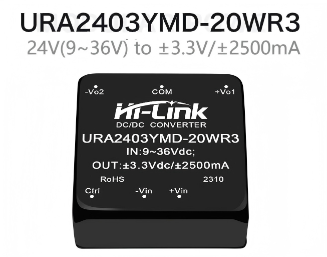
URA24_YMD-20WR3 URA2403YMD-20WR3
制造商:
Shenzhen Hi-Link
0个评价 | 0人购买
型号
URA2403YMD-20WR3
URA2405YMD-20WR3
URA2409YMD-20WR3
URA2412YMD-20WR3
URA2415YMD-20WR3
URA2424YMD-20WR3
促销
产品推荐
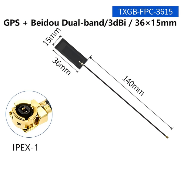
Built-in flexible FPC/PCB circuit board patch high-gain IPEX antenna
0人购买
$0.24
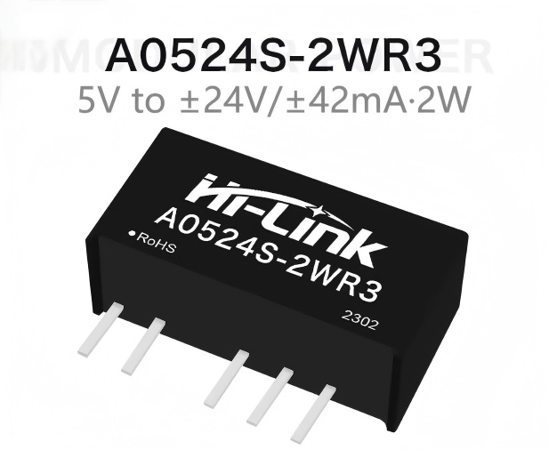
A0505S-2WR3/A0503S/A0512S/A0515S/A0524S-2WR3 Dual output 5V to 3.3V/5V/9V/12V/15V/24V 2W DC to DC power module/converter
0人购买
$0.60
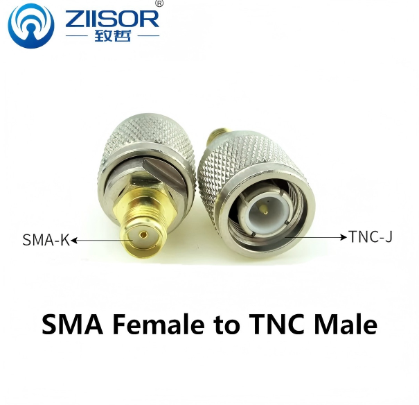
SMA-J to SMA-K adapter, N male connector, pure copper inner pin / SMA female inner hole / through adapter
0人购买
$0.59
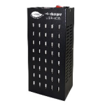
USB Multi-port Charger 40-port High-power Charging Power Supply, Suitable for Android Phones in Studios and Commercial Use
0人购买
$200.00
Full-band IPEX connector FPC built-in patch antenna PCB
0人购买
$0.34
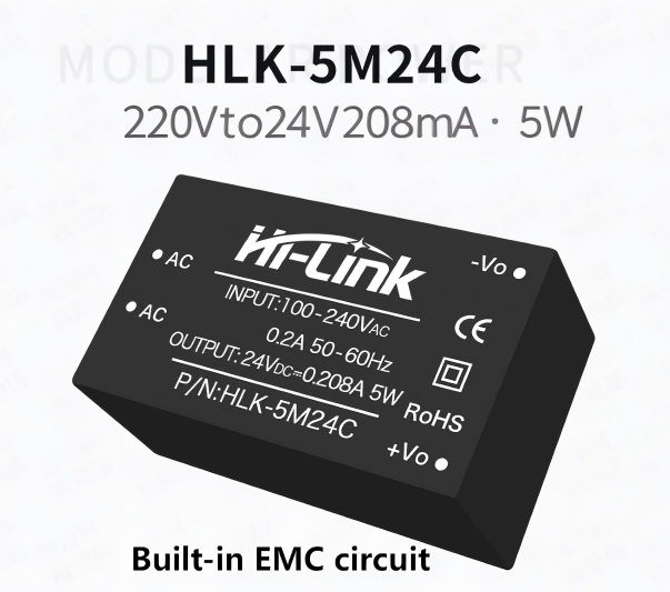
AC to DC 5W HLK-5M24C Step Down mini Power Supply Converter Module Switch Power Module Insert EMC Electric Circuit
0人购买
$1.40


购物指南
服务申明
快递
支持七天无理由退货
如果快递丢失,支持退货
如果快递损坏,支持退货
支持90天内免费换货
安全与隐私
安全付款:未经您的同意,我们不会与任何第三方分享您的个人信息。
安全的个人资料:我们保护您的隐私,确保您的个人资料安全可靠。
支付安全
与受欢迎的支付合作伙伴合作,您的个人信息是安全的。